Lab 8: Stunts!
Objective
The goal of this lab is to program the robot to perform one of two stunts: a flip or a drift. I fear that the flip stunt will require making changes to the robot’s weight distribution, something I would like to avoid at this stage. Also, repeated testing of the flip might cause damage to the robot, which can take a lot of time to fix. Therefore, I chose the drift stunt to avoid this problems and because I have high-confidence in my rotational PID controller. The drift stunt is divided into three parts. First, the robot drives forward, starting less than 4m away from the wall. When it reaches 3ft (914mm) from the wall, it will initiate a 180 degree turn. Finally, it will drive back from the wall to its original position.
Open Loop vs. Closed Loop
The drift stunt has steps that must be performed sequentially, so it makes sense for the the stunt to be implemented in an open-loop system. However, the 180 degree rotation can be implemented using the rotational PID controller, which is a closed-loop system. I addressed this issue by starting the rotational PID-controller only when the distance sensor detects that the wall is less than 914mm away. When the rotational PID-controller achieves an error of less than 5 degrees for the first time, open-loop control resumes, and the robot drives forward (back to the starting position) for 1 second, regardless of distance sensor readings. In this way, the drift implementation is a combination of closed and open-loop control.
Object-Orienting the PID Controller
I want the robot to perform the drift stunt upon receiving a BLE command. Inside of the command, I will implement all of the code needed to perform the stunt. I realized that copy-pasting all of the PID logic into one BLE command is unwieldy, so I created a PIDController class. The header file for the class is shown below:
1
2
3
4
5
6
7
8
9
10
11
12
13
14
15
16
17
18
19
20
21
22
23
24
25
26
27
28
29
30
31
32
33
34
35
36
37
38
39
40
41
42
43
44
    /**
     * Initialize PID computation
     */
    void begin();

    /**
     * Reset the state of PID computation
     */
    void reset();

    /**
     * Calculates the PID given an input at a certain time
     */
    float compute(float input, float time);

    /**
     * Returns the proportional term
     */
    float getProportionalTerm();

    /**
     * Returns the integral term
     */
    float getIntegralTerm();

    /**
     * Returns the derivative term
     */
    float getDerivativeTerm();

    /**
     * Returns the setpoint value
     */
    float getSetpoint();

    /**
     * Set new PID gains
     */
    void setGains(float kp, float ki, float kd);

    /**
     * Set new setpoint
     */
     void setSetpoint(float setpoint);
As expected of object oriented programming, much of the class is boilerplate getters and setters, so I will only discuss the interesting methods: begin, compute, and reset.
1
2
3
4
5
6
void PIDController::begin(){
  _lastTime = millis();
  _lastError = 0;
  _integralSum = 0;
  _setpoint = 0;
}
The begin method instantiate the fields needed to run compute. Since begin sets the _lastTime field needed to calculate dt, compute should be called as soon as possible after begin.
1
2
3
4
5
6
7
8
9
10
11
12
13
14
15
16
17
18
19
20
21
22
23
24
25
26
27
28
29
30
31
32
33
34
float PIDController::compute(float input, float time){

  // calculate error
  float error = input - _setpoint;

  // calculate sampling time in seconds
  float sampleTime = (time - _lastTime) / 1000.0;

  // proportional term
  _pTerm = _kp * error;

  // integral term
  _integralSum = _integralSum + error * sampleTime;
  if(_integralSum > MAX_INTEGRAL) _integralSum = MAX_INTEGRAL;
  if(_integralSum < MIN_INTEGRAL) _integralSum = MIN_INTEGRAL;
  _iTerm = _ki * _integralSum;

  // derivative term
  float dError = (error - _lastError) / sampleTime;
  _dTerm = _kd * dError;

  // combine the terms
  float output = _pTerm + _iTerm + _dTerm;

  // apply output limits
  if(output > MAX_OUTPUT) output = MAX_OUTPUT;
  if(output < MIN_OUTPUT) output = MIN_OUTPUT;

  _lastInput = input;
  _lastError = error;
  _lastTime = time;

  return output;
}
The compute method is simply a re-implementation of lab 5 in a class. The reset function serves a similar purpose as begin by instantiating fields for compute, but should be used after a cycle of PID has already been run.
Implementing the Drift
Now the PID controller is easy to use, I created a new BLE command START_STUNT. This command holds all of the code needed to perform the stunt. First, I want to use a while-loop to wait until the distance sensor gets a reading of less than 914mm. However, if the while-loop is the first thing in the command, loop-guard is reached before the sensor can obtain its first reading. I solved this problem by taking an initial reading before the while-loop. The only hardware change I made was adding masking tape to the wheels so that it can drift easier on hard surfaces.
1
2
3
4
5
6
7
8
distanceSensor1.startRanging();
while(!distanceSensor1.checkForDataReady()){
  delay(1);
}
distance = distanceSensor1.getDistance();
distanceSensor1.clearInterrupt();
distanceSensor1.stopRanging();
distanceSensor1.startRanging();
Now that an initial reading is set, I can make the robot drive forward as long as it is greater than 3ft away from the wall. I did not use the Kalman filter because it adds unnecessary complexity to the implementation.
In the code below, the execution is stuck in the while-loop as long as the robot is far enough away.
1
2
3
4
5
6
7
motorDriver.driveForward(100);
while(distance > 914){
  distance = distanceSensor1.getDistance();
  distanceSensor1.clearInterrupt();
  distanceSensor1.stopRanging();
  distanceSensor1.startRanging();
}
When the robot finally enters the 3ft range, the code moves on. At this point, the motors are stopped, but not braked. I still want the robot to slide forward while it turns. At the same time as I stop the motors, I activate the PID controller using begin. This sets the current orientation of the robot as _setpoint = 0. In the next line, I use a setter to change the setpoint to 180 degrees. Then, the code enters the closed-loop portion of the stunt as it tries to achieve the correct orientation.
1
2
3
4
5
6
7
8
9
10
11
12
13
14
15
16
17
18
19
20
21
22
23
24
motorDriver.stopMotors();
motorController.begin();
motorController.setSetpoint(180000);
bool inPosition;
inPosition = false;
while(!inPosition){
  if(firstTime){
    prevTime = millis();
    firstTime = false;
  }
  if (myICM.dataReady()){
    currTime = millis();
    dt = currTime - prevTime;
    prevTime = currTime;
    myICM.getAGMT();
    float gZ = myICM.gyrZ();
    yaw = yaw + gZ * dt;
    float pid = motorController.compute(yaw, millis());
    if(abs(yaw - motorController.getSetpoint()) < 5000){
      motorDriver.stopMotors();
      inPosition = true;
    }else{
      motorDriver.handleTurningPID(pid);
    }
You might notice that the close-loop control only stays active when the robot is not in the correct position. However, the robot is deemed to be in the correct position as soon as its rotation is within 5 degrees of the 180 degree setpoint. This means that any overshoot will not be corrected. This created the unique challenge of avoiding overshoot by all means. I will talk about how I did this in the tuning section. After the robot is in position, it drives forward for 1 second, not considering anything else.
1
2
3
motorDriver.driveForward(100);
delay(1000);
motorDriver.stopMotors();
Initial Results and Tuning
I tested the drift using the parameters Kp = 0.005, Ki = 0.000, Kd = 0.000. This was not good because the robot rotated too strongly, which caused it to veer off towards the left. I want the robot to start and end same position while moving in a straight line.
In the next test, I lowered Kp to 0.003. This time, the robot did not turn fast enough, causing it to hit the wall. By pure chance, the wall straightened the robot’s orientation, allowing it to drive back in a straight line. This behavior is not ideal and not repeatable.
From these two tests, I identified two issues:
- not turning fast enough initially to cancel its forward momentum, causing it to turn left
- overshooting the 180 degree setpoint, causing the 1 second drive back to end in the wrong location
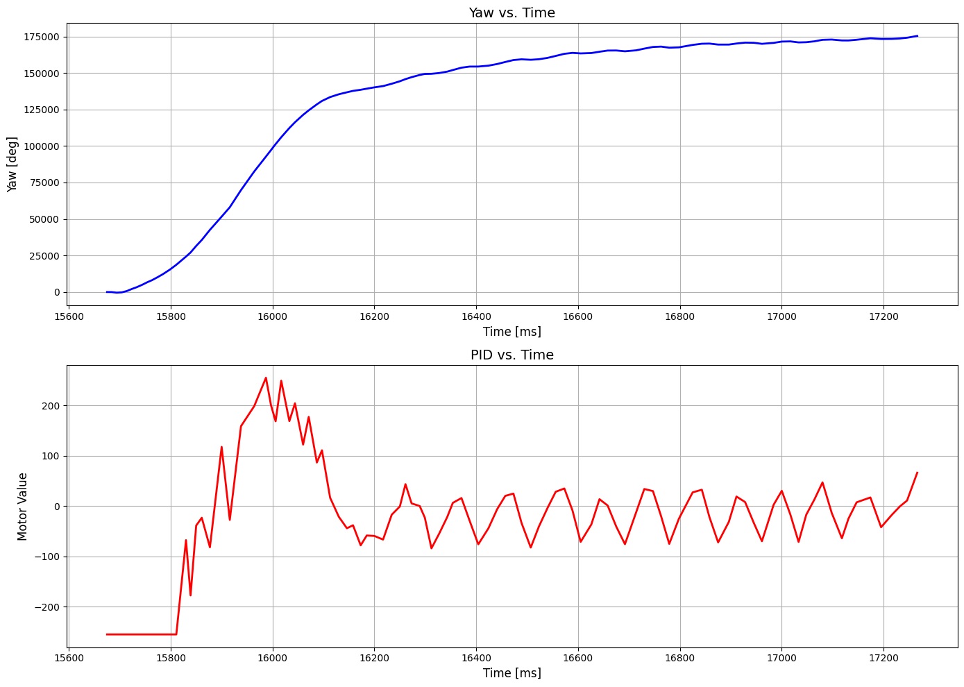
Both of these issues could be solved by adding a small derivative term into the PID controller. When the robot is about to turn, the derivative controller adds a kick to rotation, cancelling forward momentum. When as the orientation gets closer to the setpoint, the derivative controller dampens the rotation, preventing overshoot. I was happy to see that one solution was able to fix both problems. The graph below shows the yaw and motor input over time. In the beginning, the motor input shoots up to give the system a kick. As the yaw approaches the setpoint, the derivative controller comes into play, toggling the motor input until the orientation is within 5 degrees of error. 5 degrees of error was chosen because that is how much the motor drift per 2 seconds. This strategy is not the most efficient, but it prevent overshoot at all costs. There is no distance data collected at this stage because it is not used.
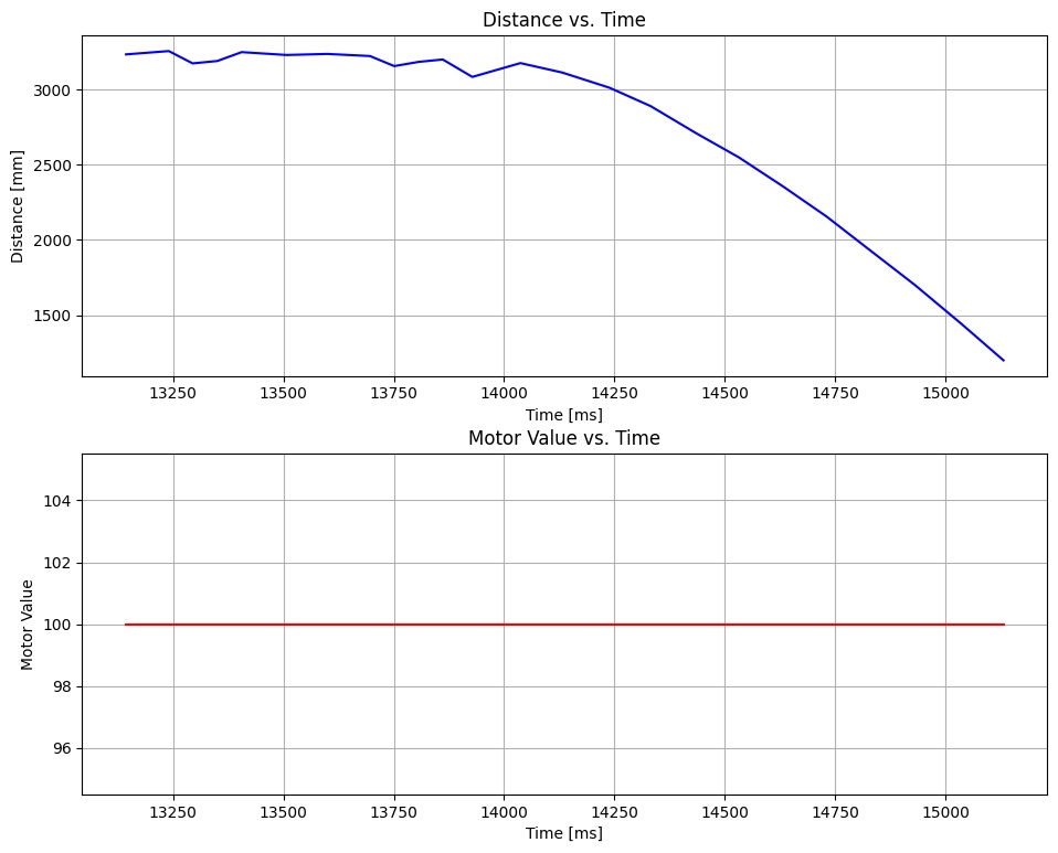
I also includes the distance data for the robot approaching the wall at a motor input of 100. There is no yaw data collected in this step because it is not used.
Here a video of 3 successful drift runs!
Conclusion
This lab was the the culmination of everything that we have worked on so far.
- Lab 1: BLE commands use to signal robot to start stunt
- Lab 2: IMU used in rotational PID controller
- Lab 3: ToF sensors used to detect distance from wall to start drift
- Lab 4: Motor drivers to drive and turn the robot
- Lab 5: Initial implementation of general PID controller
- Lab 6: Applied general PID controller to rotational PID controller
- Lab 7: Did not use Kalman filter, but could have for distance extrapolation
I thoroughly enjoyed using everything I’ve learned so far to implement this robot stunt.
References
- Special thanks to all the TAs that replaced the the broken parts on my robot!