Lab 4: Motor Drivers
Prelab
Artemis Pins
To choose pins for control on the Artemis, I considered pin functionality and physical placement on the board. Using the pin functionality datasheet, I selected four pins that support PWM output, at different corners of the microcontroller board. The pins should be as far each other as possible to minimize crosstalk. Specifically, I used pins 0, 5, 11, and 16. In the Arduino code, it is important to set the pins as output, as shown below:
1
2
3
4
5
6
7
8
9
10
11
#define PIN1 5
#define PIN2 11
#define PIN3 0
#define PIN4 16

void setup() {
  pinMode(PIN1, OUTPUT);
  pinMode(PIN2, OUTPUT);
  pinMode(PIN3, OUTPUT);
  pinMode(PIN4, OUTPUT);
}
Seperate Batteries
I powered the the Artemis and motors with seperate batteries. Motors can draw several amps of current, while microcontrollers only need microamps. If the two components used the same power source, a motor stall could cause excessive current draw, potentially damaging the Artemis. Therefore, using seperate batteries is the safest and simplest option.
Routing Paths
Longer connections cause unnecessary noise, so all wires should be as short as possible. It is difficult to determine wire length without physically placing the components in the robot. I will solder wires the drivers, attach them to the robot using zip-ties, and then solder the wires to the Artemis once everything is secured. I also made sure to use stranded wires instead of solid-core wire. Solid-core wires is easier to work with, but is more brittle than stranded wires. I don’t want the wire to break when the robot crashes into a wall.
Lab Tasks
Task 1: Connect Power and Signal Input to Driver
Power and input wires had to be soldered directly the the board. The diagram below shows to the connections.
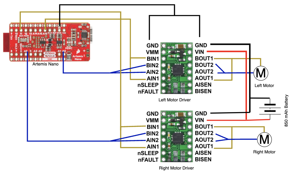
The picture below shows the soldered connections.
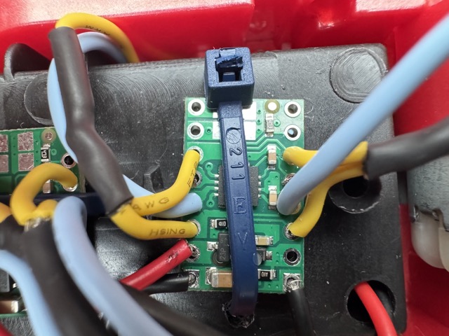
We are using two drivers to control each motor so that more current can be delivered. AIN1/2 should be shorted to BIN1/2, and AOUT1/2 should be shorted to BOUT1/2. The yellow wire on the right side connects AOUT1 and BOUT1. The blue wire on the right side connects AOUT2 and BOUT2. The yellow wire on the left side connects AIN1 and BIN1. The blue wire on the left side connects AIN2 and BIN2. It’s hard to tell from the picture, but the blue wires wrap under the board to short two adjacent pins together.
The red wire provides VIN for both drivers, and the black wire provides GND for both drivers. VIN and GND extend to the other side of the robot, where they are connected to the battery. The black wire on the bottom-right corner of the driver on the right connects to GND on the Artemis. The power supply was set to 3.7V to properly mimic the behavior of the battery.
Task 2: PWM Signals
Next, I used analogWrite commands to generate PWM signals using the Artemis. For example, here is the code that would generate a PWM signal at pin 0.
1
2
3
4
5
6
7
void loop() {
  analogWrite(PIN1, 200);
  analogWrite(PIN2, 0);
  analogWrite(PIN3, 0);
  analogWrite(PIN4, 0);
  delay(1500);
}
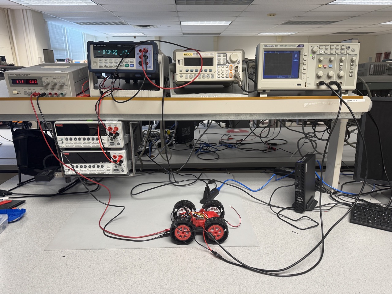
Then, I hooked up my system to the power supply and oscilloscope.
Shown below are the scope readings for testing each of the pins. The yellow signal is the pin signal and the blue signal is the active motor driver output.
Pin 0
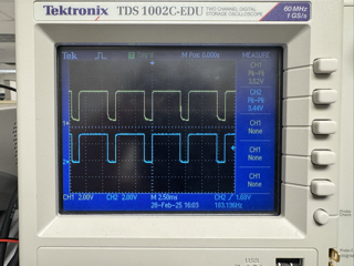
Pin 5
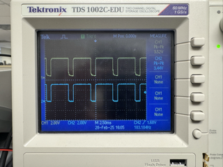
Pin 11
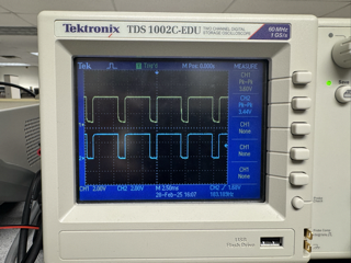
Pin 16
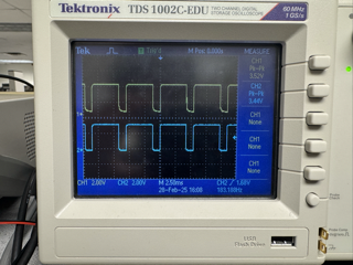
Shown below is the four channel, showing all relevant inputs and outputs for one motor driver.
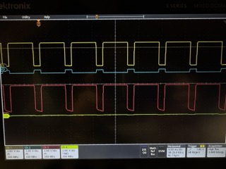
The yellow signal is IN1, the blue signal is IN2, the red signal is OUT1, the green signal is OUT2. The PWM signal is on IN2, but crosstalk interferes with the signal on OUT2. The input pins are already placed far from each other, and the crosstalk effects don’t impact OUT1 and OUT2 too much, so I decided that it wasn’t a big issue.
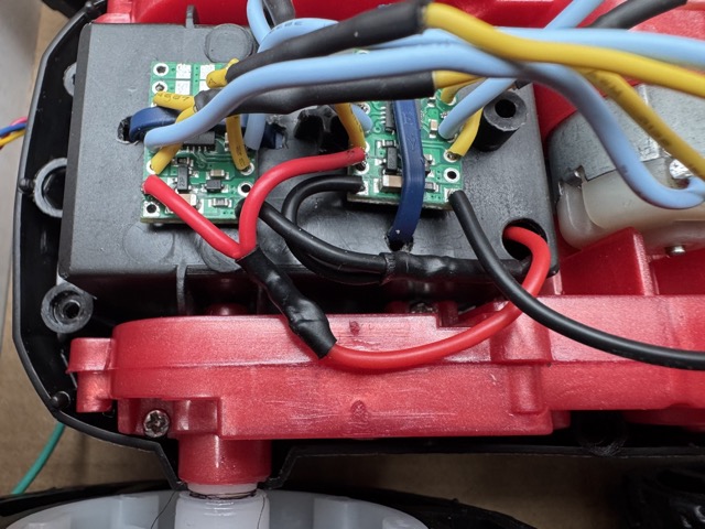
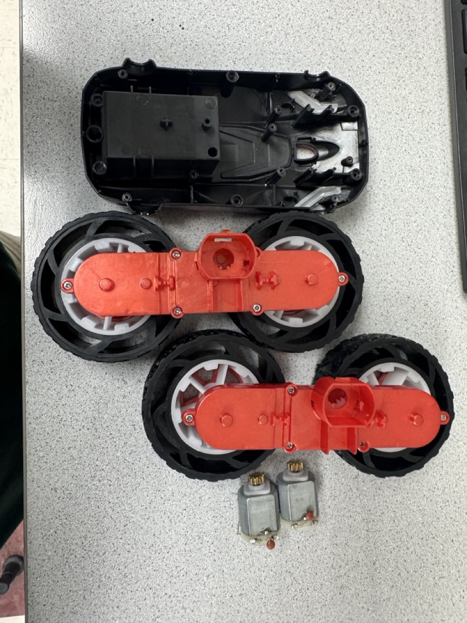
Task 3: Take Car Apart
I unscrewed the car shells and unsoldered the PCB from the motors. I will no longer need the PCB, so I discarded it. Then, I unscrewed the motor holder from the chassis removed the LEDs from the shells. Here is an image of the disassembled car.
Task 4: Motor Testing
In this video, I tested the right side motor by running it in both directions.
1
2
3
4
5
6
7
8
9
10
11
12
void loop() {
  delay(3000);
  analogWrite(PIN1, 100);
  analogWrite(PIN2, 0);
  analogWrite(PIN3, 0);
  analogWrite(PIN4, 0);
  delay(2000);
  analogWrite(PIN1, 0);
  analogWrite(PIN2, 100);
  analogWrite(PIN3, 0);
  analogWrite(PIN4, 0);
  }
Task 5: Fully Battery Powered
Disconnecting from the power supply, I powered the motor drivers using a 850 mAh battery. I used the battery connector than came with the original PCB, and the video below demonstrates the correct functionality.
Task 6: Second Motor
I repeated the process for the second motor by generating a PWM signal at the appropriate pin. I did not have to add another 850 mAh battery because a single one was enough to power both motors.
Task 7: Car Assembly
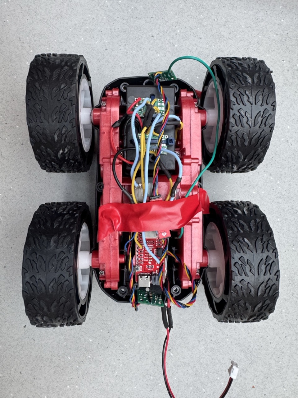
I drilled small holes through the chassis of the car so I could use zip-ties to hold down the motor drivers. The battery and Artemis are held down using velcro-tape. Wires are trimmed to the perfect length. All exposed wire was protected using shrink wrap. OUT1/2 are soldered directly to the motor terminals to reduce inductive noise. During assembly, the soldered connections broke several times, so I had to add some slack to the wires to reduce strain.
Task 8: Lower Limit PWM
The lowest PWM that the motors can achieve forward driving is 30. This minimum is becuase the motor must overcome static friction for the wheels to start moving. For PWM under 30, the motor is not able to produce enough force to overcome it. The lowest PWM that the motors can achieve turning is 70. The PWM must be higher for turning because there is more friction. The wheel spacing of the car is not ideal, so the wheels are slightly fighting against each other when turning.
Task 9: Drive Straight
I was very lucky to have motors that spin at the same rate, so I did not have to implement a calibration factor. The video below shows that my robot can move in a fairly straight line. The robot starts at the first piece of red tape. When it reaches the second piece of red tape 6ft away, it still partially overlaps with it. Although the uncalibrated motor setup is not perfect, it is good enough given the criteria of this task. The robot starts and stops several times to make testing easier (I didn’t have to chase the robot around).
Task 10: Simple Open Loop Control
Finally, I implemented some open loop, untethered control. The script commands the robot to travel in a conservative zig-zag pattern, pausing after each turn.
1
2
3
4
5
6
7
8
9
10
11
12
13
14
15
16
17
18
19
20
21
22
23
24
25
26
27
28
29
30
31
32
void loop() {

  // Delay at Startup
  delay(3000);

  // Drive Forward
  analogWrite(PIN1, 0);
  analogWrite(PIN2, 50);
  analogWrite(PIN3, 50);
  analogWrite(PIN4, 0);
  delay(1500);

  // Turn Right
  analogWrite(PIN1, 0);
  analogWrite(PIN2, 50);
  analogWrite(PIN3, 0);
  analogWrite(PIN4, 50);
  delay(1500);

  // Drive Forward
  analogWrite(PIN1, 0);
  analogWrite(PIN2, 50);
  analogWrite(PIN3, 50);
  analogWrite(PIN4, 0);
  delay(1500);

  // Turn Left
  analogWrite(PIN1, 50);
  analogWrite(PIN2, 0);
  analogWrite(PIN3, 50);
  analogWrite(PIN4, 0);
}