Lab 12: Planning and Execution
Motivation
The purpose of this lab was to program the robot to navigate through a series of waypoints in a pre-defined environment, or world. This lab builds on previous work and is the culmination of several systems (both open and closed loop) working together. Initially, I wanted to use the localization implemented in lab 11 to localize at each point, and then act according to the results. However, I hit a dead-end and had to try other methods. Eventually, I resorted to hard-coding the path. This lab report will document the roadblocks encountered during localization, describe the other methods that I tried, and present the final results. Shown below is the goal path of the robot, directly from the lab manual:
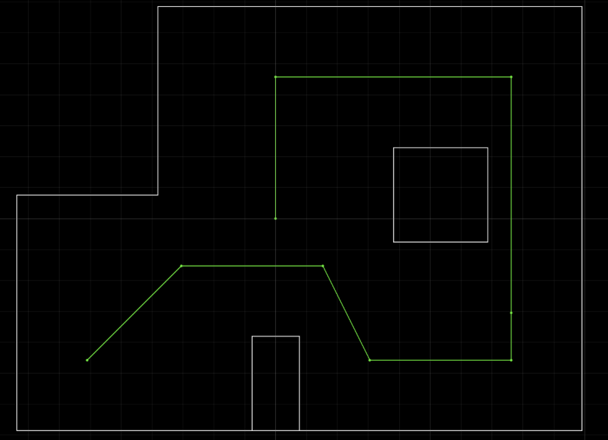
The points that I need to hit are:
- (-4, -3) <–start
- (-2, -1)
- (1, -1)
- (2, -3)
- (5, -3)
- (5, -2)
- (5, 3)
- (0, 3)
- (0, 0) <–end
Localization Attempt
I started with the ambitious goal of making my robot act similar to how it did in the simulation from lab 11.
As can be seen from the video, the robot localizes by performing an observation loop, and then performs three movements (rotation, translation/drive, rotation). The issue was that the localizations from lab 11 weren’t very accurate. I spent some time trying to improve the localization after lab 11, but wasn’t able to achieve a margin of error that would be acceptable for using localization for path planning. Shown below is one of my better localizations at the origin:
_localization.png)
There is almost a full tile’s worth of error in the prediction. This would be acceptable if localization only happened once, but instead, it must happen at 8 out of the 9 points to achieve the desired destination. Even if the localization could maintain an error bound of 1 tile, localizing 8 times could produce an error of 8 tiles in the worst case. This amount of error would be larger than the height and width of the world itself. Additionally, the localization computation can not be run on the Artemis due to memory constraints and complexity of implementation. This means that the distance sensor must be sent from the robot to the computer, and then have the localization result sent back to the robot. Referencing a calculation from lab 1, I know the the message transmission rate from robot to computer is about 63 messages per second:
\[\frac{50 \text{ messages}}{249.586\text{s} - 248.803\text{s}} = 63.857 \text{ messages/s}\]Each observation loop sends 200 messages using BLE, creating a significant amount of delay between localization and movement (in addition to the computer calculation time). For these reasons, I was did not use localization for path planning. I decided on approaching the path planning problem with a different approach: open loop using the distance sensor and rotational PID. Since I have a full view of the world, I am able to tune the robot’s movements and visually judge the result, rather than relying on a faulty localization implementation. Since this implementation does not use state estimation, Bayes filter probabilities are not necessary.
Open Loop Helper Functions
To make programming the path less painful, I create two helper functions (rotate and moveGap) to the main file and implemented a new method (brakeMotors) in my MotorDriver class.
The rotate helper method leverages the rotational PID controller to rotate the robot to a certain orientation. The deg parameter is not a delta angle from its current position, but rather a requested setpoint. For example, calling rotate(90) twice will cause the robot to rotate to 90 degrees, NOT 180 degrees.
1
2
3
4
5
6
7
8
9
10
11
12
13
14
15
16
17
18
19
20
21
22
23
24
25
26
27
28
29
30
31
32
void rotate(int deg){
  // change set point
  motorController.begin();
  motorController.setSetpoint(deg * 1000);
  bool inPosition = false;

  // rotational PID controller
  while(!inPosition){
    if(firstTime){
      prevTime = millis();
      firstTime = false;
    }
    if (myICM.dataReady()){

      // calculate yaw
      currTime = millis();
      dt = currTime - prevTime;
      prevTime = currTime;
      myICM.getAGMT();
      float gZ = myICM.gyrZ();
      yaw = yaw + gZ * dt;
      float pid = motorController.compute(yaw, millis());
      if(abs(yaw - motorController.getSetpoint()) < 5000){
        // if the yaw is within 5 percent of the set point, its good enough
        motorDriver.stopMotors();
        inPosition = true;
      }else{
        motorDriver.handleTurningPID(pid);
      }
    }
  }
}
A large source of error lies in this rotate implementation. The rotational PID needs to know when to stop, so it used an if-statement to check if the yaw has reached the desired range. However, the yaw will never reach the exact request setpoint, so I had to set the acceptable range to plus or minus 5 degrees around the setpoint. In the results, section, we see that this error causes the robot to move off-track. The next helper function that I implemented was moveGap(). The purpose of moveGap() is to drive the robot forward until it reaches a certain distance, or gap, between itself and the wall. When it reaches the requested distance, it hard brakes.
1
2
3
4
5
6
7
8
9
10
11
12
13
14
15
16
17
18
19
20
21
22
23
24
25
26
27
void moveGap(int gap){
  // start ranging
  distanceSensor1.startRanging();

  //get initial distance
  while(!distanceSensor1.checkForDataReady()){
    delay(1);
  }
  float distance = distanceSensor1.getDistance();
  distanceSensor1.clearInterrupt();
  distanceSensor1.stopRanging();
  distanceSensor1.startRanging();
  motorDriver.driveForward(50);

  // while the distance is greater than the requested gap, keep driving forward
  while(distance > gap){
    distance = distanceSensor1.getDistance();
    distanceSensor1.clearInterrupt();
    distanceSensor1.stopRanging();
    distanceSensor1.startRanging();
  }

  // when it has reached the requested distance, stop ranging and brake
  distanceSensor1.clearInterrupt();
  distanceSensor1.stopRanging();
  motorDriver.brakeMotors(200);
}
The final line of the function is motorDriver.brakeMotors() which is a new method I implemented in my MotorDriver. In order, the function performs the following tasks:
- brake both motors but setting the pins according to the data-sheet
- delay for
timeamount of milliseconds, passed in by the parameter - set all of the pins LOW
1
2
3
4
5
6
7
8
9
10
11
void MotorDriver::brakeMotors(int time){
  analogWrite(PIN1, 250);
  analogWrite(PIN2, 250);
  analogWrite(PIN3, 250);
  analogWrite(PIN4, 250);
  delay(time);
  analogWrite(PIN1, 0);
  analogWrite(PIN2, 0);
  analogWrite(PIN3, 0);
  analogWrite(PIN4, 0);
}
The reason for task 2 and 3 is that we don’t want to stall the motors for too long, as it could damage the motor and motor driver. The method allows the user to pass in a time in milliseconds depending on how much hard braking is needed to stop the forward momentum.
Open-Loop Implementation
Using my helper functions, I hardcoded the path, with comments labeling what commands are associated with each of the 9 points
1
2
3
4
5
6
7
8
9
10
11
12
13
14
15
16
17
18
19
20
21
22
23
24
25
26
27
28
29
30
    // (-4, -3)
    moveGap(300);
    rotate(-90);

    // (-2, -1) and (1, -1)
    motorDriver.driveForward(50);
    delay(2500);
    motorDriver.brakeMotors(200);
    rotate(-180);

    // (2, -3)
    moveGap(300);
    rotate(-90);

    // (5, -3) and (5, -2)
    moveGap(300);
    rotate(0);

    // (5, 3)
    moveGap(1000);
    rotate(90);

    // (0, 3)
    moveGap(1300);
    rotate(180);

    // (0, 0)
    motorDriver.driveForward(100);
    delay(1000);
    rotate(0);
Sadly, the waypoints get increasingly difficult, so I was not able to execute the full length of waypoints accurately. I still wanted to demonstrate my code working at some points in the execution, so I took two videos of the robot traversing different parts of the world. Since I used the open-loop approach, I did not have separate steps for planning and execution. Therefore, I did not need to combine screen capture and live video of the robot.
First Half
In the first video, the robot hits (-4, -3), (-2, -1), (1, -1), and (2, -3) well. Then, it overturns at (2, -3) causing it to miss (5, -3) on the way to (5, -2). From there, the robot massively overturns to the left and slams into the square structure in the world.
Second Half
In the second video, our starting position is where we ended last time, at position (5, -2). The remaining turns are all 90 degrees, so I was able to crank up the speed while still being able to hit the remaining points, although the extra speed caused massive overshoot on the origin endpoint.
Sources of Error
Although the implementation is not entirely open-loop (rotational PID and distance sensor), the hard-coded sequence of actions has several sources of error:
- the movement from (-2, -1) to (1, -1) is too far from the wall to be sensed with the ToF sensor with precision, so the
driveForward()movement is manually timed. This means that the robot will travel shorter distances for that stretch as the battery gets lower - large acceptable yaw error in the rotational PID controller causes orientation error to build up
- this version of the code does not use DMP, so gyroscope drift is a big issue
Conclusion
Although it was disappointing that I couldn’t get my localization to work well enough for path planning, I still thoroughly enjoyed this lab. Given a less academically intense semester, I would have wanted to spend more time trying to get localization to work. This lab reminded me of my robotics team in highschool, where we would program our VEX robots with open-loop autonomous routines for completing a variety of tasks. I liked how this lab felt like the culmination of everything we learned in the class. I am proud of my robot for staying intact after everything I’ve put it through. It goes to show how important having robust hardware is in a robotic system. Many thanks to all of the TAs and Professor Helbling for making this one of the most memorable classes that I have taken at Cornell. I learned so much and can’t wait to put my skills to the test after college.
References
- Jeffrey Cai for advice on calculating angles to turn from each point