Lab 1: Artemis Nano and Bluetooth
Part A: Setup and Example Programs
I needed a way to to upload code to the Artemis Nano, so I installed the Arduino IDE and Apollo3 boards manager. When I tried uploading code the board, there was an error saying that the bootloader was not found. To fix this issue, I downloaded the CH340 Driver. On MacOS Sequoia, the driver must be activated in the settings menu. (Settings->General->Login Items and Extensions->Driver Extensions). In between code uploads, the board must be re-plugged in while the code is compiling. Eventually, I got fed up with re-plugging the board, so I downgraded my system to macOS Sonoma, which fixed the issue.
The blink example (File->Examples->01.Basics->Blink) sets up the built-in LED by setting its pin as an output. In the main loop, it turns the LED on and off by setting the output pin HIGH and LOW with a 1 second delay.
The serial terminal example (File->Examples->Apollo3->Example4_Serial) starts by defining the baud rate of 115200 and a default configuration value. The baud rate is the number of signal changes that occur per second. The setup function prints out some example formatted strings. The loop function echos any serial string inputs that are received.
The temperature sensor example (File->Examples->Apollo3->Example2_analogRead) reads the analog value of the onboard temperature sensor and prints it to the serial terminal. To test this, I heated the board using a hair dryer at full heat. The example code prints the ADC value of the temperature sensor.
The microphone example (File->Examples->PDM->Example1_MicrophoneOutput) uses an FFT to find the frequency of the sound played into the microphone. I tested this using audio of a C major scale. I found that the example code doesn’t do a good job at calculating the frequency when the notes are changing, probably because it is overly-sensitive to high frequnecy noise.
The C-note detector blinks the onboard LED when the microphone detects the middle C-note (262 Hz). This program is a combination of the previous microphone example program and the the blink-without-delay sample program. Most humans are only able to tell the difference between tones more than 10Hz apart, so I gave the frequency a 10Hz margin for activating the blinking LED. The following if-statement is placed within the printLoudest() method.
1
2
3
4
5
6
7
8
9
10
11
12
13
14
// Check if the loudest frequency is that of middle-C
if(ui32LoudestFrequency > 250 && ui32LoudestFrequency < 270)
{
  if (currentMillis - previousMillis >= interval)
  {
  // save the last time you blinked the LED
  previousMillis = currentMillis;
  // if the LED is off turn it on and vice-versa:
  if (ledState == LOW)
  {
    ledState = HIGH;
  } else {
    ledState = LOW;
  }
To demonstrate the C-note detector working properly, I played a series of 5 notes. The third tone is middle C at 262 Hz. The LED only flashes when the third note is being played, which means the program is working as expected.
Part B: Bluetooth
Prelab
For the Bluetooth section of this lab, I created a virtual environment (FastRobots_ble), where I installed several packages needed to run the Bluetooth code repository. Then, I downloaded the arduino code from the course website and uploaded ble_arduino.ino to the board. The MAC address was printed to the terminal. To access the demo code, I activated the virtual environment, navigated to the ble_robot_1.2 folder, and ran jupyter lab.
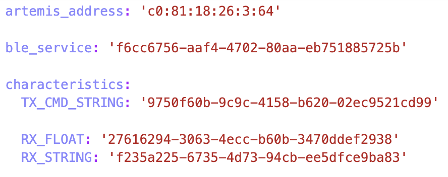
To set up the python script for connecting to the Artemis Nano, I modified the artemis_address and ble_service fields in connection.yml. The artemis_address is set to the MAC address printed to the serial terminal by the ble_arduino.ino script, and ble_service is set to the output of the python code below:
1
2
from uuid import uuid4
uuid4()
This code generates a random UUID (Universally Unique Identifier), a 128-bit number uses to identify a computer’s information.
Additionally, the BLE_UUID_TEST_SERVICE constant is set to the set ID as ble_service. Shown below is the video of the demo.ipynb file connecting to the board via Bluetooth and running come example commands.
Codebase
The BLECStringCharacteristics class is used for handling String variables provided by ArduinoBLE. The writeValue() and setValue() methods accomplish the same goal, which is to set a C-String to transmit to the computer. The valueInto() method formats the input as a proper C-String, with a null character at the end. The value() method returns the value as an 8 bit unsigned integer pointer. Similar classes for integers and floats are provided by in the ArduinoBLE library.
The Estring class (short for Enhanced String) has methods to convert between character arrays and EString objects. The clear() function empties the contents of the character array. The append() function concatenates to the end of the EString. The c_str() function returns the character array.
The purpose of the RobotCommand class is extract information from messages sent to the microcontroller that it receives via Bluetooth from the computer. The set_cmd_string() sets the command string attribute from the received message. Then, functions like get_command_type() and get_next_value() are used to extract the command and provided arguments, respectively. The extracted information is used in ble_arduino.ino in a switch-case chain to handle the different commands.
Lab Tasks
Task 1: ECHO Command
The ECHO command sends a string from the computer to the board. The board sends back an augemnted version of the string, with a prefix and postfix. the prefix and postfix are both ASCII smiley faces. First, I use the get_next_value() method to extract the value sent from the computer as a character array. Then, I clear the tx_estring_value and use the append() method to add the prefix, input message, and postfix to the string. Finally, I use writeValue() to send the string back to the computer.
1
2
3
4
5
6
7
8
  // Clear the EString
  tx_estring_value.clear();
  // Append prefix, input, and postfix
  tx_estring_value.append(":) ");
  tx_estring_value.append(char_arr);
  tx_estring_value.append(" :)");
  // Write string
  tx_characteristic_string.writeValue(tx_estring_value.c_str());
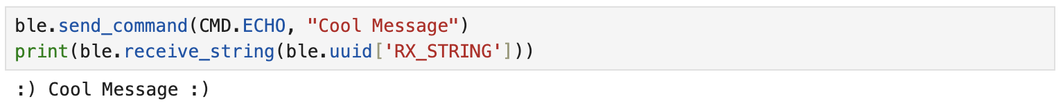
From there, I tested the command using Jupyter Notebook:
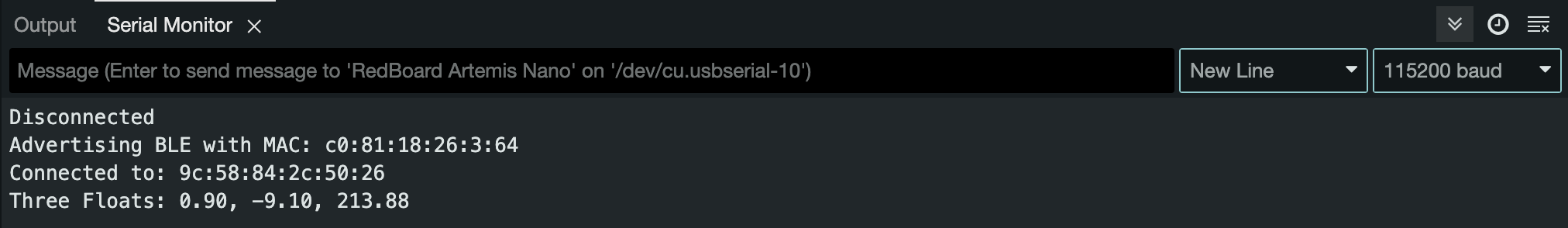
The serial terminal on the Arduino IDE also prints the message that it sends to the computer:

Task 2: SEND_THREE_FLOATS Command
The SEND_THREE_FLOATS command uses get_next_value() to extract the three float parameters that are passsed to it. The get_next_value() method can take an int, float, or char as a parameter. It will then save the data sent from the PC to the pointer location of the parameter.
1
2
3
4
5
6
7
8
9
10
11
12
    // Extract the next value from the command string as a float
    success = robot_cmd.get_next_value(float_a);
    if (!success)
        return;
    // Extract the next value from the command string as a float
    success = robot_cmd.get_next_value(float_b);
    if (!success)
        return;
    // Extract the next value from the command string as a float
    success = robot_cmd.get_next_value(float_c);
    if (!success)
        return;
The program will only try to get a next float value if the previous one was successful. If get_next_value() ever fails the command will end. The program then prints out the extracted floats, and prints them to the serial terminal.
Task 3: GET_TIME_MILLIS Command GET_TIME_MILLIS is the first new command I have to add to the program. First, GET_TIME_MILLIS must be added to the switch-case chain and the commandTypes enumeration in the arduino code. Also, it must be added to the cmd_type.py file in the python code. The command uses the millis() command to set the time variable. Then, it uses append() to write to the transmission string.
1
2
3
4
5
6
7
8
// Initialize time variable
double time;
time = (double)millis();
// Clear the String
tx_estring_value.clear();
// Create String
tx_estring_value.append("T:");
tx_estring_value.append(time);
Similar to the ECHO command, the program prints out the message that it is sending back to the computer to the serial terminal. Shown below is the the computer recieving the message.

Task 4: Notification Handler
The notification handler is responsible for detecting when the board has sent a message, at which point it will parse it, and print it. The notification handler will need to display time and temperature in later sections of the lab. There is an if-statement that checks if temperature data was received, and prints the required fields.
1
2
3
4
5
6
7
def notif_handler(uuid, byte_array):
    time = ble.bytearray_to_string(byte_array)[2:12]
    temp = ble.bytearray_to_string(byte_array)[15:]
    output = 'Time(s): ' + str((float)(time)/1000)
    if temp:
        output += ';  Temp(C): ' + temp
    print(output)
Now, I can run the GET_TIME_MILLIS command without a print() statement after it because the notification handler takes care of it.

Task 5: TIME_LOOP Command
The TIME_LOOP command is essentially the same as the GET_TIME_MILLIS command, except it does it in a loop for 2 seconds. It repeated aquires an individual time value and sends it. Simplify the data transmission rate calculation, I changed the loop from 2 seconds to capping at MAX_SAMPLES = 50.
1
2
3
4
5
6
7
8
9
10
for(int i = 0; i < MAX_SAMPLES; i++){
  // Create string
  tx_estring_value.clear();
  tx_estring_value.append("T:");
  tx_estring_value.append((double)millis());
  // Write string
  Serial.print("Sent back: ");
  Serial.println(tx_estring_value.c_str());
  tx_characteristic_string.writeValue(tx_estring_value.c_str());
}
The notification handler comes in especially handy in this case becuase there are so many values that need to be printed.
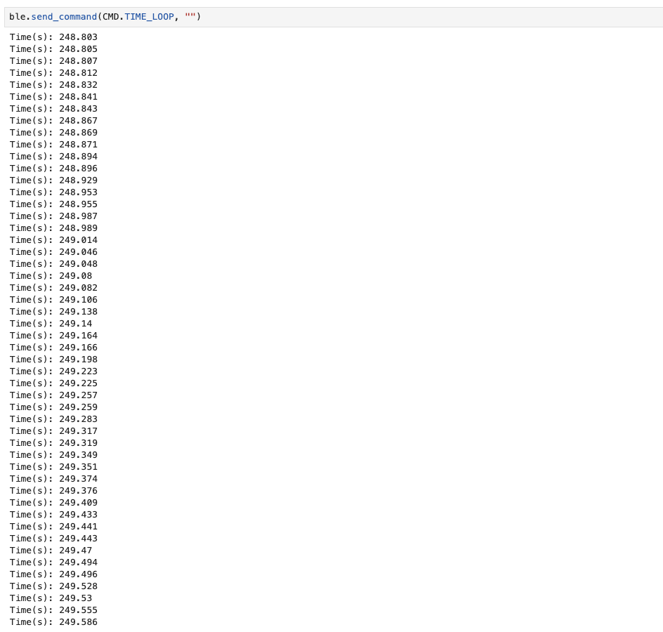
From this result, we can tell that the effective data transfer rate is
\[\frac{50 \text{ messages}}{249.586\text{s} - 248.803\text{s}} = 63.857 \text{ messages/s}\]Task 6: Time Array
Next, I tried a new way of collecting and transmitting the time data. Instead of collecting and then transmitting over and over, I collected all of the time data in an array and then transmitted the array. This change was made in TIME_LOOP. The for-loop below shows the time_array being filled out. The for-loop for sending the array data (in SEND_TIME_DATA) has the same structure.
1
2
3
4
// Add MAX_SAMPLES amount of time samples
for(int i = 0; i < MAX_SAMPLES; i++){
  time_array[i] = (double)millis();
}
The MAX_SAMPLES constant is set to be 50, but can be increased for a larger time array.
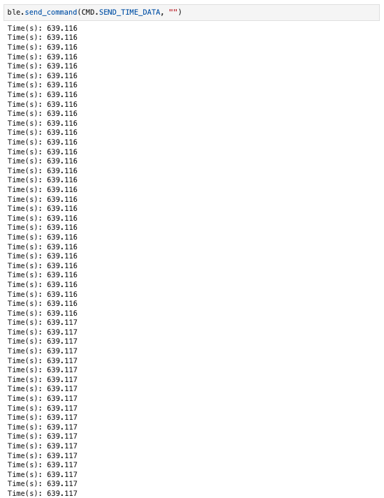
To calculate the sampling rate, we need to increase MAX_SAMPLES because there is not consecutive message transmissions are less than 0.001 seconds apart. Increasing MAX_SAMPLES to 200, we can see the same time in 60 messages, which means that 60 messages takes 0.001 seconds to send.
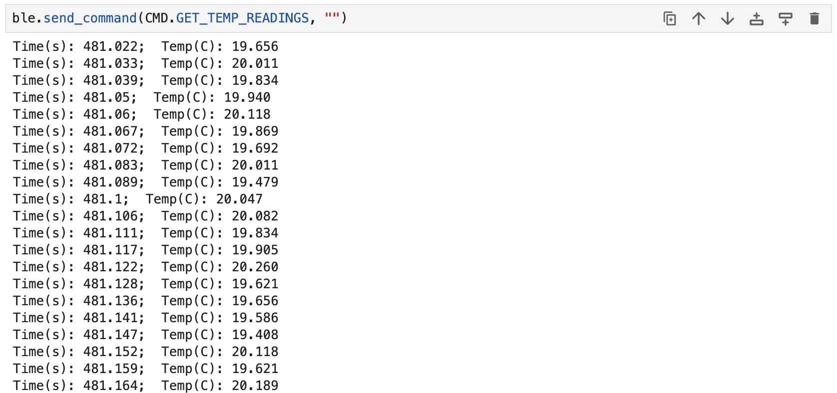
Task 7: Temperature Array
The GET_TEMP_READINGS command is a combination of TIME_LOOP, SEND_TIME_DATA, and the AnalogRead Example.
1
2
3
4
5
6
7
8
9
10
11
12
13
14
// Add MAX_SAMPLES amount of time and temp samples
for(int i = 0; i < MAX_SAMPLES; i++){
    // Required for ADC reading
    #ifdef ADCPIN
    int external;
    // Reads the analog voltage on the selected analog pin
    external = analogRead(EXTERNAL_ADC_PIN);
    Serial.printf("external (counts): %d, ", external);
    analogWrite(LED_BUILTIN, external);
  #endif
  // Get time and temp from functions
  time_array[i] = (double)millis();
  temp_array[i] = getTempDegC();
}
Task 8: Differences Discussion
In task 5, individual points of time data are transmitted in-between sampling (108 messages per second). In task 6, the entirety of the sampling happens before anything is transmitted (60000 samples per second). This is done using two for-loops, the first one for collecting time data in an array, and the second one for transmitting the array data. This means that the received time data in task 6 represents when the data is recorded, NOT when it is sent.
The task 6 method had a higher sampling rate than the task 5 method. The downside of task 6 is that it requires more arduino memory space to save the time_array list, whereas task 5 can keep rewriting values to the same variable.
The Artemis board has 384 kB of RAM. To calculate how many temperature values the board can stored, there are several assumptions that I must make. First, I rashly assume that the program uses all 384kB of the RAM to store temperature data (ignoring all other variables and times asscociated with the temperature data). Second, I assume that a single temperature data points can be represented with a double. Finally, I assume that maxing out on RAM (or achieving near full capacity) will not cause odd behavior in the program.
\[\frac{384 \text{ kB}}{4 \text{ B}} = 96000 \text{ temperature values}\]This calculation shows us that the Artemis Nano can hold a maximum of 96000 temperature values at a maximum, even though this is an over-estimate.
Discussion
In this lab, I learned how to set up a development environment for the Artemis Nano on a macOS. I also learned how to leverage the ArduinoBLE library to set up Bluetooth connection between my computer and the board. I created commands on the board to respond to requests from the computer, and implemented a notification handler to parse data coming from the board. Finally, I learned that I should bundle data into single, larger transmissions rather than sending several shorter transmissions.